Table of Contents
MFCitizen @Cardiff
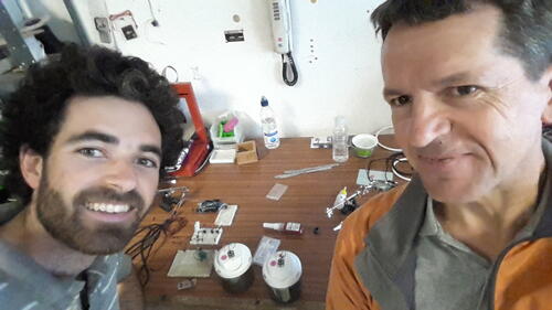
Paul Granjon & Michka Mélo, September 7th-9th, 2016
Abstract
This was our second working session with Paul, after the one held in Brussels in 2014 on DIY supercapacitors from dead batteries.
We decided to focus this second session on the topic of microbial fuel cells (MFCs), a renewable electricity production device in which electrogenic bacteria digest organic matter in an anaerobic environment.
Even though the MFCs power output are very low (typically 100 W/m3, or 50-100 microwatts for the 0.5L container of the Mudwatt kit, they are very interesting because:
- they may be made 100 % from municipal solid waste and renewable resources (mud, organic waste) which can be found everywhere ;
- their operation can be quite continuous, compared to other renewables.
After few prototyping sessions and a first workshop led on the topic, we got actual voltage and current measurements - even though they were quite low to be of any use. Exploring possible designs for a Power Harnessing System (PHS) harnessing and storing these little amounts of energy to make them usable seemed quite necessary. We also needed to build more accurate and more easy-to-use performance tracking system (PTS) than a simple manual multimeter, to monitor efficiently the voltage and current output of the MFCs.
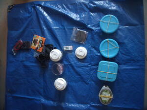
We therefore decided to start from a solid ground, the Mudwatt kit. Paul ordered three of them, which we set up. The one filled up with a smelly damped clay slush from the beach took-of on the second day of the Hackathon, and its LED was blinking twice every second on the end of the fifth day. The other two had not started yet at the end of our 3-days hackathon, but Mudwatt says they take at least 3-7 days to start.
While the Mudwatts were starting up, we worked on the PHS design and fabrication. We explored many different ways detailed below, including small surface-mount DC/DC boost converters, as well as through-hole-components-based circuits such as Joule Thiefs. Some further work needs to be done there to find the appropriate solution for the MFCs.
We also worked on the PTS design and fabrication. The INA-219 current sensor connected to an Arduino Uno proved to be a just-accurate-enough good starting point, even though we had some voltage measurement issues. Paul also explored possible ways to make the data collected by the Arduino automatically updated and logged online, including the brand-new Arduino Cloud, and some older lower-level possibilities.
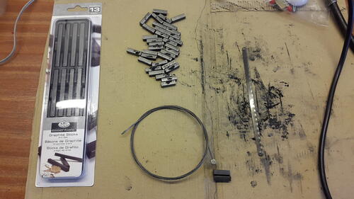
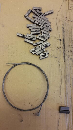
Finally, Paul made an electrode out of graphite rods from an arts & crafts shop and an old bicycle stainless stell cable.
Next steps include further monitoring of the Mudwatts, further research and prototyping on the PHS, more tests to improve the accuracy of the INA-219 current sensor, further exploration of Arduino-to-web connexions, as well as home-made MFC prototyping.
Introduction
This was our second working session with Paul, after the one held in Brussels in 2014 on DIY supercapacitors from dead batteries.
We decided to focus this second session on the topic of microbial fuel cells (MFCs), a renewable electricity production device in which electrogenic bacteria digest organic matter in an anaerobic environment.
Even though the MFCs power output are very low (typically 100 W/m3, or 50-100 microwatts for the 0.5L container of the Mudwatt kit, they are very interesting because:
- they may be made 100 % from municipal solid waste and renewable resources (mud, organic waste) which can be found everywhere ;
- their operation can be quite continuous, compared to other renewables.
You can find here some notes about previous experiments on MFCs.
The objectives of this session were:
- to set up Paul’s brand new Mudwatt kits, which are science education MFCs kits for kids.
- The reasoning behind this is to get some previously designed MFCs up and running, for the sake of self-confidence :) and to start our research on waste-based MFC from a solid ground.
- to reverse engineer the very simple and elegant power harnessing system (PHS) of Mudwatt kits, which allows a LED to blink or a clock to run on the energy output of a single Mudwatt.
- The reasoning behind this is to get a previously designed PHS up and running to start our research on (e-)waste-based PHS from a solid ground.
- to design a performance tracking system (PTS) for the Mudwatt or comparable MFCs, allowing to monitor in a relevant way their voltage and current outputs.
- This PTS will allow us to prototype many different designs from various waste sources, and see how they behave over the long-term, without going into time-consuming manual measurement protocols.
- make a graphite electrode out of graphite rods for art & crafts.
- This is a first step towards waste-sourced non-corroding electrode materials.
1. Mudwatt kits
1.1 Getting mud for the Mudwatt
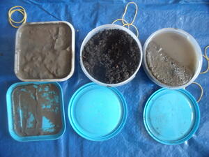
We started the working session by walk to the seaside in Barry (Wales, UK), to collect:
- a kind of clay slush
- a more sandy slush
… to feed the Mudwatts that Paul got previously.
We also took some soil from Paul’s garden to feed the third Mudwatt.
1.2 Filling the Mudwatt
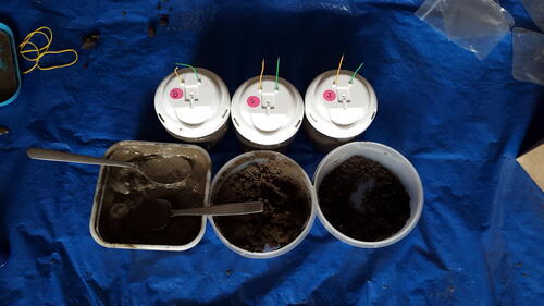
We filled the Mudwatts first thing when we arrived at the workshop, following Mudwatt’s manual.
We labeled them as follows:
- the clay-slush one was called B (for “Boue”)
- the sand-slush one was called S (for “Sable”)
- the garden soil one was called J (for “Jardin”)
1.3 First performance measurements
A couple of hours later, we measured, with a basic multimeter:
- several dozens of mV on the B and S Mudwatts.
- about 300 mV on the J Mudwatt.
During our Skype call later on, Johann from Flower Power Pot told us that these initial value might not mean anything relevant, as the microbial community has to build up first.
1.4 First LED blinks !
Mudwatt’s manual tells us that the MFC may take 3 to 7 day to start-up sufficiently for the LED to blink.
Paul was performing a quick open-circuit voltage measurement on the Mudwatts in the middle of the afternoon of day 2, when he noticed that the open-circuit voltage across the B Mudwatt had jumped from several dozens mV to 0.4 V.
He decided to plug the Hackerboard with its red LED on the B Mudwatt, to see what happened… and it blinked ! One time per second !
The B Mudwatt, made from Barry’s bay clay-slush, was ready to the power the LED around 30 hours after setup !
1.5 Performance measurements
When we came back on the morning of day 3, the LED of the B Mudwatt was still blinking at roughly one time per second.
We decided to use our freshly prototyped PTS (the INA219 current sensor on an Arduino Uno, see section 3 for details) on the B Mudwatt to see how much power was coming from out there.
Right after connexion, the load voltage was 1.03 V, and the current measured was around 10 mA, but decreasing very quickly.
The current value slowly decreased for a few hours, stabilizing somewhere between 0.3 and 0.4 mA. FYI, the sensitivity of the INA219 current sensor is 0.1 mA.
The load voltage value stayed quite stable, at 1.03 V. We realized afterwards that this value was probably fake (see section 3 for more details). The open-circuit voltage of the B Mudwatt after monitoring the performance for several hours through our PTS was 0.3 V, according to a basic multimeter.
1.6 Performance measurements may be “tiring” the MFC
After monitoring the performance of the B Mudwatt for several hours through our PTS, we put back the Hackerboard & LED on the B Mudwatt, and it did not blink for a while, like if the monitoring had sucked up all its energy. At that moment, the open-circuit voltage across the MFC was around 0.3 V.
About an hour later, it was back to one blink every approx. 4 seconds.
Then, we disconnected the Hackerboard for a couple of hours to bring the B Mudwatt home. When we connected it back, the blinking frequency had jumped to one every second or so.
Several hours later that night (day 3), the frequency was almost twice blink per second, and so it was the following morning.
By the evening of day 3 (around 6 pm), none of the other S & J MFCs were blinking.
2. Power Harnessing System (PHS)
2.1 What is Mudwatt’s PHS design ?
Mudwatt’s PHS - also known as its Hackerboard - is super simple: it consists of a single five-leads chip, connected to one or two small capacitor, and the load, which can be an LED or a clock.
Info on the five-leads chip was hard to get. An old version of Mudwatt’s manual was refering to a now dead forum of Keegotech.
Nowhere in the manual, nor in the old forum thread scavenged from Discs archives could we find the reference of the component. There was just a reference to a “charge-pumping” activity.
By analysing thoroughly the situation, Paul noticed that the component had the same packaging and number of leads of a charge-pump I had seen in a paper from Meehan and Gao, the Seiko 882-Z.
We got the confirmation from Johann during our Skype call that it was this component that they used, as they named it at the end of their Instructable.
However, Paul had already noticed that the production of the Seiko 882-Z seemed to be discontinued.
We therefore needed to look for alternatives.
2.2 First alternatives to Mudwatt’s PHS design
Several scientific papers detail PHS designs for single MFCs.
- Meehan and Gao designed a PHS based on a Seiko 882-Z charge pump, connected to a 2.2 F B0820-2R5335-R Cooper/Bussman supercapacitor and controlling MOSFET switches activating a ST Microelectronics L6920DB Boost Converter.
- Shantaram et al. designed a PHS based on a Maxwell 4F [@? TODO] supercap in series with the Max1797 DC/DC converter.
- Thomas et al. designed a PHS based on a 1:20 < 1 V transformer, connected to an ultra-low-voltage LTC3108 step-up converter, connected to an output 680 uF capacitor and an storage 0.4 F supercapacitor. This PHS is the one that the Flower Power Pot project is trying to replicate at the moment.
Meehan and Gao’s design is very interesting, as it could be described as a “Mudwatt PHS on steroids”, starting as low-power, and powering stronger bursts thanks to the boost converter. Sadly, it also relies on the Seiko 882-Z discontinued charge pump.
Shantaram et al.’s design seems quite promising too, as it connect directly the MFC to the DC/DC converter through a supercapacitor. However, as we realized later on, their quite peculiar manganese-based MFC design with sacrificial electrode has a way higher output voltage, which allows to charge the supercapacitor without any charge pump. Our regular Mudwatt-like MFC design does not allow for such high voltages, and the capacitor charge will be stuck at the MFCs output, which is likely to be a few hundred mV at best.
Thomas’ design is quite different than Meehan and Gao’s, using a small 1:20 coupled-inductor transformer instead of a charge pump. However, as we realized as Paul was cutting the PCB for the freshly ordered LTC3108 converter on his CNC, both recommended chips for the transformer seemed not to be available anymore, or available only in large quantities (1000+).
Anyway, we:
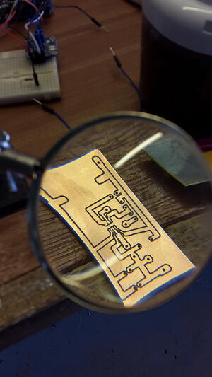
- cut a first version of a PCB for the LTC3108 DC/DC converter, to be refined.
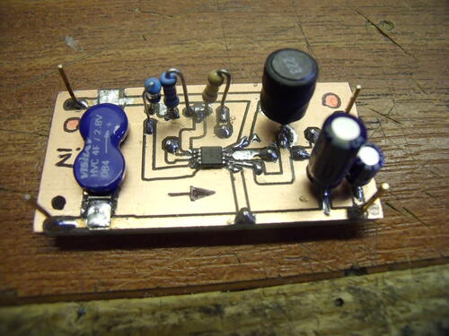
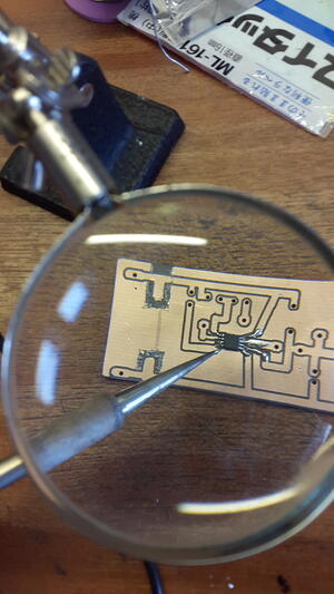
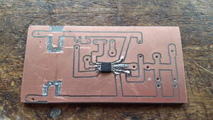
- cut a first version of a PCB for the full Shantaram et al. circuit, ordered and soldered all the components on it.
In addition to that, we:
- assessed the use of a Beam robotics Solar Engine 1381 design as a MFC PHS;
- explored in length the use of a Joule Thief circuit as a MFC PHS.
2.3 Cutting a PCB for the LTC3108 DC/DC converter (Thomas et al. PHS)
The week before, Paul had ordered a small component called LTC3108, a small DC/DC converter featured in the power harnessing system from a paper by Thomas et. al, advised and selected by Johann for the Flower Power Pot project.
As it is a surface-mount component, it is not possible to use it in a traditional breadboard for prototyping, as its leg are too small.
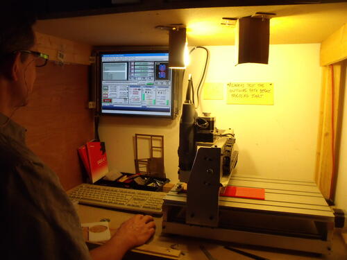
Therefore, Paul proceeded to cut a small support for it with the CNC in the workshop.
Roughly, these were the steps of the process:
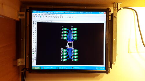
- opening Eagle, the PCB design software Paul has on his machine
- looking for a template for the LTC3108 in Eagle’s library
- it might help to check the component’s datasheet for a packaging reference, such as SSOP-16 in this case. This is how it was described in the Eagle library - and not by the component reference.
- if you do not find it, check online, with keywords such as “Eagle library file LTC3108 Linear technology”
- sometimes, templates come up in large .zip files with components from a manufacturer, such as a Linear-Technology.zip. Then, you have to check if your component is in it.
- open the template in Eagle, and check that it is the right one.
- if you are using, as we did, a fiber-glass support with a copper layer on top, keep in mind that were you cut, you are removing the copper, and therefore the electrical connexion.
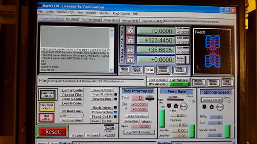
- export the G-code to Eagle’s plug-in connecting it to the CNC
- beware that the G-code is defined in the right unit - metric or imperial system.
- make the CNC run
- this part of the process is quite technical, as the dimensions there are challenging Paul’s CNC sensitivity. Paul had to try out several times, and play with :
- the number of passes of the CNC on each cut
- the spacing between these number of passes
… to obtain a PCB with proper unbroken wide-enough tracks on which to solder the LTC3108.
As we realized that we would not get the 1:20 transformer by the end of our working session, Paul switched to the realization of the Shantaram et al. circuit before he had a first fully working version of this PCB.
2.4 Building Shantaram et al.’s PHS
This was basically the same process as stated above, with a digression in updating Eagle to read the library files for the Maxim1797 layout, and getting compatibility issues with the CNC plug-in.
Last but not least, soldering the small surface-mount Maxim1797 and its tiny leads to the chip was quite a challenge, which Paul has adressed with years of hand-made-machines crafting experience. He drops a spot of superglue below the chip to paste it to the PCB, and then solders each lead with a tiny soldering iron tip.
This being said, god bless through holes components !
Before that, we also had to shop the components.
We had to replace the Maxwell 4 F supercapacitor, which we could not find on the RS shop for a next-working-day order, by a Vishai 4 F supercapacitor.
In their paper, Shantaram et al. refer to a 0.28 microA/h leakage current for the Maxwell 4 F supercapacitor. When we looked at the datasheets on the Maxwell website, we found 2.8-28 microA leakage current for supercapacitor of similar capacity (0.1-10 F). Was there a mistake on Shantaram et al.’s paper ? Was the production of this “leakage-proof” supercapacitor discontinued ? Did we miss it ?
There were no 4 F supercapacitors with a leakage current of 28 microA on RS anyway, so we went for the Vishai one.
All the other components were found properly.
FYI, we did not tested the circuit before the end of our session.
2.5 Beam robotics “Solar engine” PHS
When discussing about a lower-tech charge pump circuit, Paul mentionned the Beam robotics circuits, which are often made of basic through-hole off-the-shelf components, and are powered by renewables.
Paul identified a circuit which may be interesting for our application : the Beam Robotics Solar Engine 1381.
This very smart and simple circuit, which I took quite a bit of time to fully understand (lacking some basic transistor dynamics understanding), works quite well, but is limited by the storage capacitor voltage, which depends on the solar cell voltage.
Solar cells voltage being way higher than MFC and comparable to the motor’s operating voltage, there is actually no need for a DC/DC voltage multiplication in the circuit - just a charge accumulation in the storage capacitor.
This circuit therefore cannot be applied directly to the MFC. We need a voltage multiplier to charge our capacitor sufficiently high to power a LED, or any other kind of load.
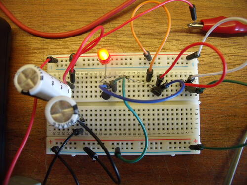
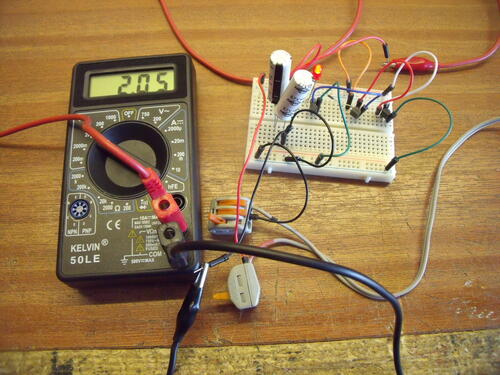
Anyway, we prototyped and tested the circuit (replacing the motor by a LED), and it worked perfectly well. A 2200 uF proved to be way to small to really see the circuit effect on a LED. We replaced it by a 10 F supercapacitor, and it worked great, lighting the LED for several minutes after cutting having charged the supercapacitor and shut down the power supply.
2.6 Through-hole-components-based charge pump
As we realized that none of our circuits will be completed during our Hackathon for various reasons - missing components, high voltage operation, I tried to go for a through-hole-components-based charge pump.
The Wikipedia page on charge pumps refered to a quite simple circuit which could be made of simple components.
We were skeptical regarding the ability to design a charge pump operating at low voltages and low currents with basic through-hole components, but wanted to give it a try anyway.
In the process of understanding a bit more how to design it in details, I got diverted by some Joule Thief suggestions in Youtube’s sidebar. I decided to follow this path.
We should definitely go back to charge pumps design later anyway.
2.7 Joule Thief PHS
2.7.1 Literature review
Joule Thief (JT) are simple through-hole-components-based converters which allow to power a 3.3 V LED from a used-up approx. 1 V AA cell. Its operation is pretty well described in this video.
According to Watson, a quite motivated and skilled JT explorer, typical JT draws out 70-90 mA from the battery to give 15-20 mA to the LED. Its efficiency is therefore quite low, below 50 % for most designs, some reaching about 60 % when performing really well. Watson’s supercharged JT reaches even higher levels, close to 70 %. Efficiency seem to worsen on low loads according to this source.
When digging into literature, it seems that JT designers mostly focus on energy efficiency, at the expense of high current consumption. As our MFC provide both low-voltages and low-currents (0.3 V and 0.3 mA according to our latest measurements of the B Mudwatt), we have to focus on the design of a very low power JT.
Fortunately, Watson, a quite motivated JT explorer already paved the way for a very low power JT. From this various blog posts on the topic (here, here and here) and on general description of JT dynamics (here, here, here, and here), as well as his replies to our comments, we got quite good advice.
Regarding the resistor connecting the cathode of the MFC to the feedback winding of the coil, we have to adjust - and probably reduce - its value to a point at which max LED brightness is achieved. Performing a Maximum Power Point tracking may be a good idea, according to Watson. Be careful when reducing, because if the resistor goes to zero :
- the circuit will not oscillate.
- feeding directly the transistor’s base from the battery + can damage the transistor’s emitter-base junction at high currents.
Regarding the coil, we have to reduce the value of the DC resistor of the primary winding well below 1 ohm (< 0.25 ohm is even better), by using:
- fewer turns…
- …of thick wire (or several parallel wires)…
- …around a highly-permeable ferrite coil (which will generate a magnetic field more efficiently, and does not impact the DC resistor).
- Cores advised reference include the Faire-Rite 2673002402 “RFI suppressor sleeves” or the YJ4100eTC. We can find similar ones at the end of defunct keyboard and mouse cables.
- Esoteric shapes of cores are not necessary.
- 30 AGW wire (thinner) has 0.104 ohm per foot resistance, when 24 AWG wire (thicker) has 1/4 of this resistance, so thicker wire may help. There are tables indicating wire resistance per diameter (AWG).
- According to Watson, as the energy amount fed to the LED can be calculated as E = 0.5 * L * I^2, it is more important to reduce the resistance and increase the current (squared) by using less wire, than increase the inductance of the coil by increasing the number of turns.
- The feedback winding carries little current, it is only here to turn the transistor on and off, so its DC resistance is not critical. However, it seems that increasing the turns of the feedback winding increases sensitivity at low voltage. Be careful, though : if the voltage across the output exceeds the emitter-to-base reverse voltage (usually 5 V), then the transistor may be killed ! To avoid this issue, unwind turns from feedback winding, or wind more turns on primary winding.
- The target inductance of the coil value should be around 100-250 microH (milliHenris ?). With 24-26 AWG wires, this means 7 to 12 turns around 3/8-1/2 inches cores. A lower inductance will increase the oscillating frequency, which may then interfere with the AM frequency range. Moreover, the higher the frequency, the higher the losses in the toroid.
- Air cores, which I liked for their simplicity, does not seem to be very appropriate, as they increase the DC resistance of the coil.
Regarding the transistor, we should pick one which can handle switching very high currents at very low voltage with very low losses. This means it has to:
- have high current gain (beta), 500 or more ;
- have a good current gain (beta) hold up at high current, falling way beyond 100 ma ;
- capable of managing high peak currents (minimum of 0.5 A, even higher if possible) ;
- have a low Vce(sat) (collector-emitter tension at saturation) < 0.25 V at high currents (200-400 mA) ;
- have a low DC resistance, which relates very much to Vce(sat), which is the voltage drop between collector-emitter tension at saturation - when the transistor’s gate are fully open.
- maybe having a high emitter-to-base reverse voltage is a good point, to allow for lower voltage sensitivity.
Watson directly advised us (in reply to our comments) BC547-B or C for their high current gain, and then the 2SK170 JFETs for operation at low voltages and currents. Other advised references from his posts include :
- 2N4401, PN2222A or BC337-25, which can handle up to 0.5 A peak current.
- Even better ones include 2SD5041, KSD5041, 2SC2500D, ZTX1048A, SS8050, BC639 and NTE11, which
- can manage a 1+ A peak current,
- have a very low Vce(sat),
- have a good gain hold-up at high current.
- S9014 also has a very high current gain.
- 2N3904, 2SC1815 and BC547 should be avoided.
Watson also advised us to add a 10 uF capacitor across the + and - of the battery. In one of his posts, he has written that it may help the circuit oscillate.
Other random and sometimes contradictory advice from Instructables to run low voltage JTs include :
- multiplying the number of turns by 5
- disconnecting the flat spot of the LED from the - of the battery, and connect it to the base of the transistor instead.
There are many other designs to explore such as this one or this one, with many more components than the basic JT, but which could operate at very low voltage (we do not know about the current though).
2.7.2 First prototype and next steps
While searching all the information mentionned above, we wanted to do a quick test with a basic JT design.
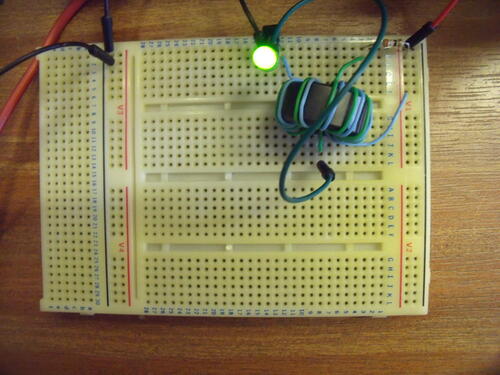
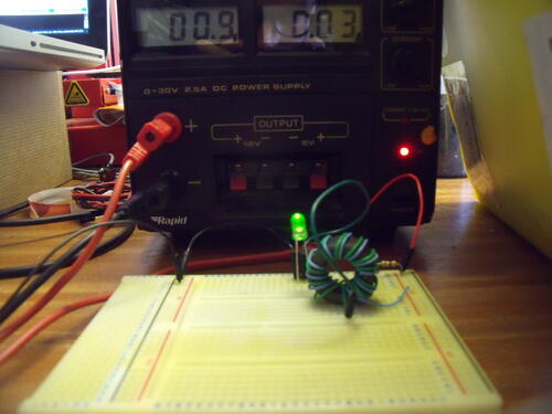
We therefore built a simple one picking the circuit design here and the transistor reference and the number of turns here.
Here are the main parameters of our JT :
- 2 windings of 10 turns of wire scavenged from a RJ45 network cable ;
- on a approx. 2cm O.D. coil ;
- with a PN2222A transistor ;
- a 1 k (and then 300 and 39 ohm, see below) resistor
- on a standard green LED.
I played around with the resistor and the adjustable power supply, and noticed that the voltage at which the LED would light up was getting lower when I reduced the resistance in series with the feedback winding. It went down from 1.8 V (about the same as the operating voltage of the LED without JT) at 1 kOhm to about 0.4 V at 39 ohm for the very first little point of light.
However, when using the 39 Ohm resistor, the current jumped up to about 30 mA, according to the power supply, which is not what we are aiming for.
Watson advised us to use the current limiting feature of the power supply to simulate the low-current of the MFC. This is going to be our very next step, as well as trying to lower the resistor even more to get to a 0.3 V LED light-up, as it currently seems to be the operating voltage of our MFC. Playing with the 10 F capacitor across the power supply should also been done quite quickly.
If we fail, we may try :
- to build a coil with lower DC resistance, use Litz wire for very low current, or maybe replace it by another transistor as Watson suggested in of its posts.
- to get one of the best transistors advised by Watson to have all the best possible parameter values (high current gain, good current gain hold up at high currents, low Vce(sat) and low DC resistance).
It would also be good to see how a (super)capacitor behaves at the output of a JT: does it charge ? Maybe a diode in series with the capacitor might help, to avoid it discharging in the JT when its voltage oscillation reaches its low point ?
If we go for several LEDs at the output, then we should read this piece from Watson.
2.8 Next steps
More generally, we may need to get one step back, and look for general info on DC/DC converter, to understand the whole variety of architectures, and see if one might fit better our needs than another. So far, we proceeded more by imitation, but there may be other ways around Buck converters (could be 95 % efficient), Boost converters (could be 70-90 % efficient) or other kind of DC/DC converters. Tracks to explore here and here.
We also sent an email to Mudwatt to ask how they were going to deal with the Seiko 882-Z being discontinued. Wait and see.
Watson also advised us just to put our MFCs in series to reach good voltage levels without loosing energy in the conversion process. This will have to be considered if converting gets to hard.
3. Performance Tracking System
3.1 Why INA219 current sensor ?
When looking for a way to automatically measure the output of our Mudwatt and non-Mudwatt MFCs, Paul identified the INA219 current sensor for performance measurement - available on Adafruit.
During our e-mail exchanges with Johann, he had shared with us his bad experience with Arduino monitoring of the MFCs.
His interpretation of the highly variable performance results he obtained was that the Arduino was at best not precise enough, and at worst interfering with electrical activity in the MFC. He encouraged us to drop Arduino measurement of the MFC, and look for other ways.
Paul picked up the INA219, because he thinks that the interference may be lower, at least above its claimed sensitivity threshold of 0.1 mA = 100 microA.
Let’s give it a try.
3.2 Setting-up the INA219
The very first step of the set-up was to solder some pins on the INA219.
Then, we connected it to an Arduino Uno following the very good doc on Adafruit’s website.
We had to install the INA219 library provided by Adafruit on Arduino.
After debugging some connexion mix-up (inverting I2C communication pins), we could measure realistic voltage and current test values provided by a small circuit made of a resistor connected to the adjustable power supply of the workshop.
We tested it right away on the J Mudwatt, and the low power values measured at the beginning declined quite quickly (as usual when measuring MFCs) until they went below the sensitivity threshold.
We disconnected the J Mudwatt.
In the evening of the same day (day 2), we performed another trial on the J Mudwatt, and got only zeros, suggesting that the MFC had not recovered yet from our previous measurement.
3.3 Performance measurement on the B Mudwatt
See sections 1.5 and 1.6
3.4 Issues with load voltage measurement
After disconnecting the sensor from several hours of B Mudwatt monitoring on day 3, we still had 1.03 V on the Arduino serial monitor, suggesting that this value was fake from the beginning.
We measured the load voltage across a resistor powered by the lab’s adjustable power supply, and the values returned as load voltage were not matching what the power supply was saying.
We have to investigate further on that issue.
One reason might be that the load voltage (around 0.3 V according to open-circuit multimeter voltage measurements) is under the sensitivity threshold for load voltage measurement, as the total range is 16 V.
A next step could be to perform again a full test with the adjustable power supply, and see if we can observe sensitivity issues on voltage measurement in that setting.
If this indeed seems to be a sensitivity issue, another next step could be to see if we can play around with the calibration methods (or write a new one) for a better sensitivity at low-voltages.
3.5 Arduino Cloud
Paul connected his brand new Arduino chip with on-board Wifi chip to the Arduino cloud through his Arduino account, using their step-by-step guide.
He could get a LED status updating live thanks to their example code, but no logging options seemed available at that date.
3.6 Arduino-to-web connexion
Paul explored some Arduino-to-web low-level tools, as an alternative to the Arduino Cloud. He managed to get the value of a variable resistor displayed on a locally-accessible HTML page.
Further explorations will be performed to make it reachable from the World Wide Web.
4. Home-made MFCs
4.1 Graphite electrode
Paul built a graphite electrode of out graphite rods we bought at The Works, an Arts & Crafts shop.
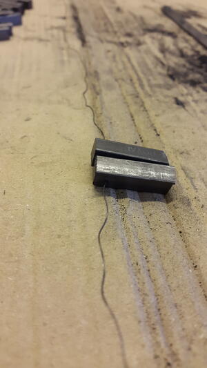
He cut down the rods in smaller chunks, drilled them, and used an old bicycle stainless steel cable to assemble them like a collar.
Then, he tightened them up with a second bit of bicycle staineless steel cable (a choice of material advised by Johann, from the Flower Power pot project).
A quick multimeter test showed that the overal resistance of the assembly was about 3 ohms.
Paul will build a similar second electrode, and then make a DIY MFC with some of the remaining clay slush - the one we used for the high-performing B Mudwatt.
5. Conclusion & Next steps
It was again a quite pleasant and productive 3-days hackathon.
We were quite happy to see one of the Mudwatt kits light up after two days of operation, and reaching a quite good frequency (2 blinks per second) at the end of the fifth day.
We explored and open many tracks regarding the Power Harnessing System (PHS), and went down a few of them:
- Paul made some PCB’s for Thomas et al’s and Shantaram et al’s PHS.
- We contacted Mudwatt for
- We explored alternative PHS designs, including Beam robotics simple and elegant design, and some deep Joule Thief reading.
Regarding the Power Tracking System (PTS):
- We tested the INA-219 current sensor spotted by Paul, and (almost) successfully measured the performance of our working Mudwatt, with an Arduino.
- Paul tested Arduino Cloud as a remote data monitoring and logging tool, and explored some more low-level options connecting directly Arduino to an HTML web page.
Regarding the prototyping of a home-made MFC, Paul built a first electrode out of graphite rods from an Arts & Crafts shop and old bicycle stainless steel cable.
Next steps include:
- Monitoring the performance of the three Mudwatts;
- Further prototyping and testing on the Joule Thief front;
- Further reading on other DC/DC converting architectures;
- Continuing the online discussions with Watson and Mudwatt related to the PHS;
- Pursuing the INA-219 testing and fine tuning, especially on the load voltage front;
- Pursuing the online data monitoring and logging explorations, especially on the existing low-level Arduino-to-web tools.
6. Acknowledgments
We owe a big thank you to :
- Johann from the Flower Power Pot project, who got us started on several of the tracks explored here;
- Watson, who gave us a lot of advice on designing a JT PHS.
- Keegan from Mudwatt who replied to our questions on the Mudwatt kit design.
