Analogue interface to the CEED
see > Cerf Notes
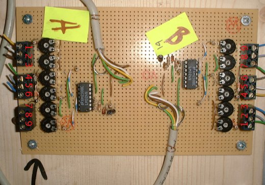
this is the prototype board…
the black arrow points to the input that i have modified. the wire link joins inputs 8 and 9. the stretch sensor should be across inputs 7 and 8. I have tried to set the values of the pots to be about right - BUT so many things could be wonky. Instructions for oscilloscope tuning can follow if you have such a thing on hand……
the cable attached to the A side of the board is then attached to a CERF and the standard cerf input capturing software is started (see the Cerf Notes page, I think).
this is a circuit diagram…
when its running, the output looks something like this


